|
The information contained in this document is intended for the sole use of Canadian Challenger owners and is strictly proprietary and confidential.
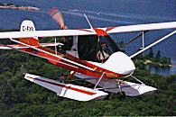
You will get the best rudder response by installing the cables to the most inboard holes of the rudder horns. As the rudder is flight critical, use AN (aircraft grade) cotter pins to attach them, not the safety pins that come with the kit. The rudder will touch the elevator at full deflection on the ground but will have clearance in flight. Also ensure that when you install the elevator push rods, that their length is set to achieve 60% up elevator and 40% down. This will give 45 degrees of up travel and 30 degrees of down travel when the push rods are installed in the uppermost hole, closest to the elevator. Aileron stick forces can be adjusted to a light and sensitive 'feel' by turning the 4 aileron cable turnbuckles where they attach to the sticks equally to a slightly loose adjustment. Too tight will increase aileron effort significantly. Always ensure however, that at least seven threads of each turnbuckle are engaged. Torque from the propeller will create a slight yawing to the left. A small trim tab riveted onto the left side of the rudder with deflection to the left will correct it. Be sure that the trim tab does not interfere with elevator travel. Pitch trim can be adjusted in flight with the flaperons. The flaperon trim speed range can be adjusted by lengthening or shortening the aileron push rods. If you need additional adjustment and don't wish to remove or add weight in the nose, add a trim tab to both (not just one) elevators. As hours accumulate, the various pivot and attach points in the elevator linkage will become loose and require adjusting to remove the slack. If too much play accumulates, mild elevator flutter will result if a combination of high speed and trim adjusted for hands off flight exists. If you encounter this in flight, immediately decrease the throttle and pull back on the stick to slow down. Replacing the elevator pins with AN drilled shank bolts, castle nuts and cotter pins, done up tight enough to add a little friction, will keep the free play from developing into a flutter. Ensure that the shank of the bolt, not the threads (which could cut) bears on the actual hinge. You can also deflect one elevator upwards slightly with the other slightly downwards by adjusting the push rods to achieve a difference of four degrees. That will load both sides in flight and eliminate free play and flutter. These fixes don't preclude proper periodic adjustment. One of the best flight instruments in existence costs nothing, and is extremely valuable as it will show you instantly if you are correctly coordinating your use of rudder and stick. This "instrument" is called a yaw string and is an old glider and fighter plane trick that works only on aircraft that have no prop wash on the windshield. Simply tape a 3" length of wool to the lower center of your windshield and it will give you all the information that a ball would, yet remain in your line of sight like a 'heads up' display. A second strand at the top of the windshield will provide the same information to the rear seat occupant. There have been a couple of instances of people installing their propellers backwards. Make sure you check for proper rotation before your first flight. The Challenger uses a cog belt reduction because it offers several advantages over gearboxes. The rubber belt provides the same positive engagement as a gearbox but substantially dampens vibration, running smoother and quieter. It also does not have an oil bath so can be started without preheating in the coldest winter temperatures. Installation must be done properly using the following procedure. Install the reduction drive upright using a drop of Loctite on the threads of each of the Allan screws. Install the lower pulley and then mark a line across the bolt head and onto the pulley with a felt pen so that a quick glance later during inspections will tell you if the bolt has loosened. Loosely install the belt over the 2 pulleys and tighten the tensioning bolt until the desired tension is attained. At this stage, you will need to set it slightly loose as tightening the castle nut will further tighten the belt. The final result should not be tight, but not loose enough to be in danger of slipping a cog. You should be able to push and pull the belt fore and aft slightly on the top pulley with some effort. Too tight will cause excessive heat and premature bearing failure. Too loose can damage or skip cogs. When the tension is about right but slightly on the loose side, torque the large castle nut to 125 ft/lbs. - TIGHT! At the same time you must ensure alignment of the castle nut for insertion of the cotter pin. Frequently you will find that tightening the castle nut will cause the belt to over tighten, requiring further adjustment. When the tension is correct, snug up the nut on the top tensioning bolt and Loctite it to lock it in place. Certain brands of belts tend to tighten during operation, so the tension should be checked after flight as well as before. The cog belt should run true on the top pulley. If the belt tracks aft of centre it could be because it was set too tight thus preventing the prop shaft from coming up to horizontal when the large castle nut is tightened. In this case loosen the belt slightly. Tracking aft may also be a sign that the redrive needs shims - check the Service Bulletin. With proper adjustment, these belts are extremely reliable however we recommend that you install a new one every 100 hours or once each year. For the Gates 9608M50 GT2 belts the service live is extended to 200 hours or two years. There is also a shelf life to belts so always use a new one. You should check that the throttles are initially set correctly by taking off the air filter and verifying that the slide in each carb is reaching the bottom and top stops. When the throttle is at idle there should be a clicking noise when the slides bottom after being lifted and released. When both are adjusted correctly at idle, open the throttle to maximum and check that both slides are equal and all the way up. When all is correctly set, pinch the small metal adel clamps slightly (with pin nose or vice grip pliers) that retain the throttle cables along the fuselage so that the cables do not slip from that adjustment. Temperature swings between seasons can cause these to loosen. Slipping (unequal) cable adjustments will create a difficult to diagnose tuning problem. Before you start the engine for the first time and particularly before the first flight, take some 2" duct tape and tape over the inboard ends of the wing spars (front and rear) and the aileron leading edge tube. There may be some rivet mandrels inside and they will eventually make their way to the open end and fall out, almost certainly damaging your propeller in the process. After you have flown 20 - 30 hours, you can take the tape off for good and at that time you will find out if you saved yourself prop damage as the bits will be stuck to the tape. When you have installed the enclosure, you will find that there is an aluminum angle on the ceiling just behind the windshield. It is unlikely to ever cause a problem, but in extreme turbulence if you happened to have your seat belt off or very loose and were not wearing a helmet, it is possible that this angle could cause a head injury. Please take the time to tape some protective padding over this angle to avoid any possibility of a problem. There is one point of great importance that should be emphasized as we have seen one owner install them backwards, not realizing the critical importance of having them installed as shown in the manual. The lower strut black (Rony) brackets that attach to the fuselage, must always be installed with the head of the bolt on the outside of the fuselage against the bracket and the nut inside the fuselage against the main longeron. To do it backwards will greatly weaken the attach point so that it could eventually fail and cause a catastrophic accident. The Challenger was designed to be easily de-riggable and as a result is supplied with fasteners and safeties that can be disassembled by hand. If you do not need this feature, we recommend that you positively fasten all attach points on the stab struts, wing struts, jury struts and spar with AN bolts and hardware. This will eliminate minute amounts of play, give a more solid feel and improve response. Remember that this is a 'pusher' aircraft. Make sure that any items that could become loose are lock wired with aircraft quality lock wire. This includes the air filter and the exhaust springs. Lock wire, lock wire pliers (available at most aircraft supply houses) and Loctite, a liquid locking compound placed on bolt threads before assembly and available in varying strengths (available in good auto parts stores) are important items in your tool box. Do not develop the habit of using the aileron gap as a tray for tools while working on the engine. Sooner or later you will forget to remove them and your propeller will suffer the consequences. We also recommend that before the first flight, you have 2 inspections done. Do one yourself, and then have a second, knowledgeable person who was not involved in the assembly of your aircraft do the last one. This helps identify any mistake you may have made in assembly that you believe to be correct. Finally, have someone who is already familiar with the Challenger perform the first flight.
To learn and see more order our comprehensive information package and video! |